- 您现在的位置:买卖IC网 > Sheet目录1228 > MAX4273EVKIT (Maxim Integrated Products)EVAL KIT FOR MAX4273
�� �
�
�3V� to� 12V� Current-Limiting� Hot-Swap� Controllers�
�with� Autoretry,� DualSpeed/BiLevel� Fault� Protection�
�If� the� sensed� current� is� still� high� after� the� startup� timer�
�expires,� the� MOSFET� gate� is� discharged� completely� as�
�described� below.�
�In� normal� operation� (after� startup),� the� fast� comparator� is�
�used� as� an� emergency� off� switch.� If� the� load� current�
�reaches� the� fast� comparator� threshold,� the� device� quickly�
�forces� the� MOSFET� off� completely.� This� could� happen� in�
�the� event� of� a� serious� current� overload� or� a� dead� short.�
�The� fast� comparator� has� a� 350ns� response� time� and� dis-�
�charges� GATE� with� a� 1mA� current.� Given� a� 1000pF� gate�
�capacitance� and� 12V� gate� voltage,� the� MOSFET� will� be�
�off� in� about� 12μs.� Any� additional� capacitance� connected�
�between� GATE� and� GND� to� slow� down� the� startup� time�
�also� increases� the� turn-off� time.�
�In� the� MAX4273,� CEXT� goes� high� impedance� during�
�the� fast� discharge.� This� reduces� the� effective� capaci-�
�tance� on� GATE� if� a� capacitor� is� used� between� GATE�
�and� CEXT,� and� allows� the� MOSFET� to� quickly� turn� off.�
�In� turn,� this� allows� adjustment� of� the� MOSFET� charging�
�time� without� affecting� the� fast� discharge� rate,� although�
�it� does� affect� the� slow� discharge� rate.�
�The� MAX4271/MAX4272� fast� comparator� threshold� is� set�
�to� four� times� the� slow� comparator� threshold� (i.e.,� 200mV).�
�The� MAX4273� fast� comparator� threshold� is� set� to� 200mV�
�by� connecting� RTH� to� GND,� is� disabled� by� connecting�
�RTH� to� IN,� or� is� adjustable� by� an� external� resistor� con-�
�nected� to� IN� (see� Fast� Comparator� Threshold� (RTH)� ).�
�Latched/Autoretry�
�The� MAX4271� MOSFET� driver� stays� latched� off� after� a�
�fault� condition� until� it� is� reset� by� a� negative-going� pulse�
�on� the� ON� pin.� The� MAX4272� is� periodically� turned� on�
�after� a� fault� condition� with� a� timeout� duration� set� by� an�
�external� timing� capacitor� on� CTIM.� The� MAX4273� has� a�
�selectable� latched� mode� or� retry� mode.� Connect� CTIM�
�to� IN� to� set� the� device� in� latched� mode,� or� use� an� exter-�
�nal� capacitor� at� CTIM� to� set� the� retry� timeout.�
�Pulse� ON� low� for� 20μs� (min)� to� restart� after� a� fault�
�(MAX4271/MAX4273� in� latched� mode).� Negative� pulses�
�are� ignored� during� autoretry� (MAX4273� in� autoretry�
�mode,� or� MAX4272).�
�The� capacitor� on� CTIM� affects� the� MAX4272’s� retry�
�timeout� period� (time� the� part� is� shut� down� after� an� over-�
�current� event)� and� the� startup� time� (see� the� Electrical�
�Characteristics� ).� The� retry� timeout� period� is� fixed� at� 32�
�times� the� startup� time� in� order� to� minimize� power� dissi-�
�pation� in� the� external� MOSFET� in� case� of� a� short-circuit�
�condition� (see� MOSFET� Thermal� Considerations� ).� This�
�is� not� an� issue� for� parts� latched� off� during� a� fault� condi-�
�tion� since� they� stay� off� until� commanded� on.� The�
�MAX4273� configured� in� retry� mode� has� a� separate�
�startup� timer� capacitor� (CTON)� and� retry� timeout�
�capacitor� (CTIM).� This� allows� the� user� to� change� the�
�ratio� between� startup� time� and� retry� timeout� period.�
�Status� Output�
�The� status� output� is� an� open-drain� output� that� goes� low�
�under� the� following� conditions:�
�?� During� the� UVLO� delay� period�
�?� In� startup�
�?� Forced� off� (ON� <0.6V)�
�?� In� an� overcurrent� condition�
�?� In� the� retry� timeout� period� (or� latched� off,� for� the�
�latched� parts)�
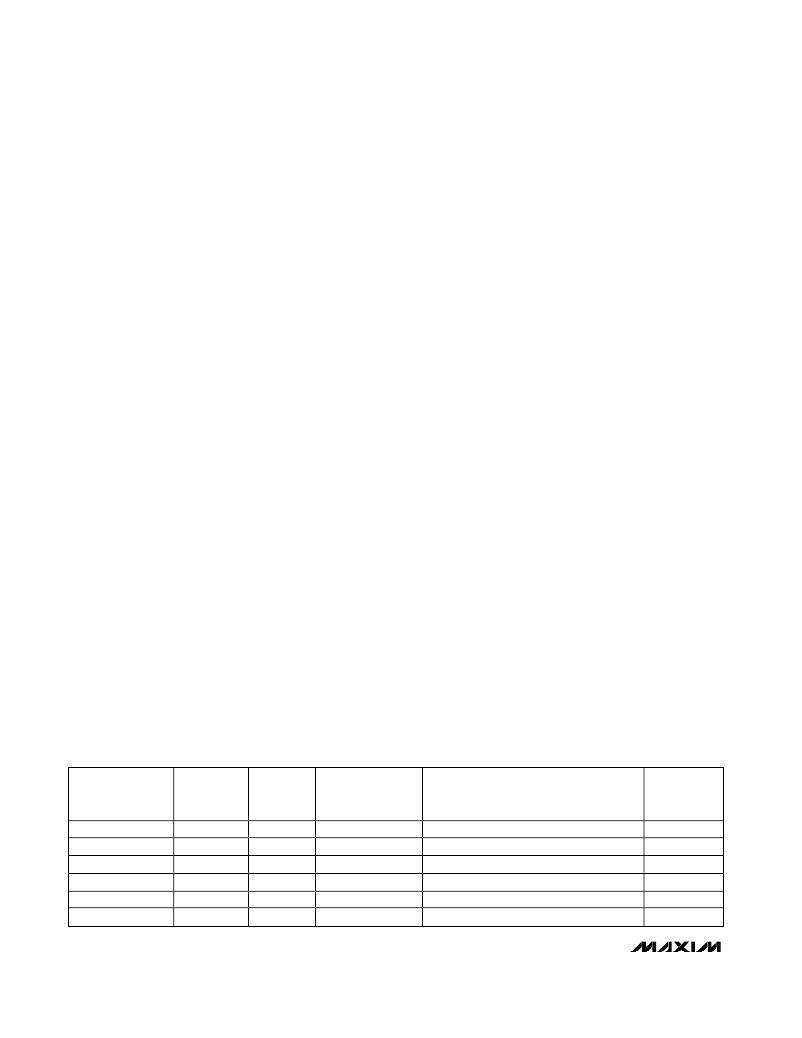
�STAT� is� high� only� if� the� part� is� in� normal� mode� and� no�
�faults� are� present� (Table� 1).� Figure� 5� shows� the� status�
�(STAT)� output� timing� diagram.�
�Over/Undervoltage� Lockouts�
�The� UVLO� prevents� the� MAX4271/MAX4272/MAX4273�
�from� turning� on� the� external� MOSFET� until� V� IN� exceeds�
�the� lockout� threshold� (2.25V� min)� for� 150ms.� The� UVLO�
�protects� the� external� MOSFET� from� insufficient� gate�
�drive� voltage.� The� 150ms� timeout� ensures� that� the�
�board� is� fully� plugged� into� the� backplane� and� that� V� IN�
�Table� 1.� Status� Output� Truth� Table�
�IN�
�UVLO� DELAY�
�PERIOD�
�Yes�
�X�
�X�
�X�
�X�
�No�
�PART� IN�
�STARTUP�
�X�
�Yes�
�X�
�X�
�X�
�No�
�ON� PIN�
�X�
�X�
�Low�
�X�
�X�
�High�
�OVERCURRENT�
�CONDITION�
�X�
�X�
�X�
�Yes�
�X�
�No�
�PART� IN� RETRY-TIMEOUT�
�PERIOD� (OR� LATCHED� OFF� DUE� TO�
�OVERCURRENT� CONDITION)�
�X�
�X�
�X�
�X�
�Yes�
�No�
�STAT� PIN�
�(STATUS)�
�Low�
�Low�
�Low�
�Low�
�Low�
�High�
�14�
�______________________________________________________________________________________�
�发布紧急采购,3分钟左右您将得到回复。
相关PDF资料
MAX4278EVKIT-SO
KIT EVALUATION FOR MAX4178,4278
MAX44265EVKIT#
KIT EVAL FOR 44265
MAX4754AEVKIT+
KIT EVAL FOR MAX4754
MAX4810EVKIT+
KIT EVAL FOR MAX4810
MAX4886EVKIT+
KIT EVAL FOR MAX4886
MAX4948EVKIT+
KIT EVAL FOR MAX4948
MAX4983EEVKIT+
KIT EVAL FOR MAX4983
MAX4989EVKIT+
EVALUATION KIT FOR MAX4989
相关代理商/技术参数
MAX4274ABESA
功能描述:运算放大器 - 运放 Integrated Circuits (ICs)
RoHS:否 制造商:STMicroelectronics 通道数量:4 共模抑制比(最小值):63 dB 输入补偿电压:1 mV 输入偏流(最大值):10 pA 工作电源电压:2.7 V to 5.5 V 安装风格:SMD/SMT 封装 / 箱体:QFN-16 转换速度:0.89 V/us 关闭:No 输出电流:55 mA 最大工作温度:+ 125 C 封装:Reel
MAX4274ABESA+T
功能描述:运算放大器 - 运放 RoHS:否 制造商:STMicroelectronics 通道数量:4 共模抑制比(最小值):63 dB 输入补偿电压:1 mV 输入偏流(最大值):10 pA 工作电源电压:2.7 V to 5.5 V 安装风格:SMD/SMT 封装 / 箱体:QFN-16 转换速度:0.89 V/us 关闭:No 输出电流:55 mA 最大工作温度:+ 125 C 封装:Reel
MAX4274ABESA-T
功能描述:运算放大器 - 运放
RoHS:否 制造商:STMicroelectronics 通道数量:4 共模抑制比(最小值):63 dB 输入补偿电压:1 mV 输入偏流(最大值):10 pA 工作电源电压:2.7 V to 5.5 V 安装风格:SMD/SMT 封装 / 箱体:QFN-16 转换速度:0.89 V/us 关闭:No 输出电流:55 mA 最大工作温度:+ 125 C 封装:Reel
MAX4274ABEUA
功能描述:运算放大器 - 运放 Integrated Circuits (ICs)
RoHS:否 制造商:STMicroelectronics 通道数量:4 共模抑制比(最小值):63 dB 输入补偿电压:1 mV 输入偏流(最大值):10 pA 工作电源电压:2.7 V to 5.5 V 安装风格:SMD/SMT 封装 / 箱体:QFN-16 转换速度:0.89 V/us 关闭:No 输出电流:55 mA 最大工作温度:+ 125 C 封装:Reel
MAX4274ABEUA-T
功能描述:运算放大器 - 运放
RoHS:否 制造商:STMicroelectronics 通道数量:4 共模抑制比(最小值):63 dB 输入补偿电压:1 mV 输入偏流(最大值):10 pA 工作电源电压:2.7 V to 5.5 V 安装风格:SMD/SMT 封装 / 箱体:QFN-16 转换速度:0.89 V/us 关闭:No 输出电流:55 mA 最大工作温度:+ 125 C 封装:Reel
MAX4274ACESA
功能描述:运算放大器 - 运放
RoHS:否 制造商:STMicroelectronics 通道数量:4 共模抑制比(最小值):63 dB 输入补偿电压:1 mV 输入偏流(最大值):10 pA 工作电源电压:2.7 V to 5.5 V 安装风格:SMD/SMT 封装 / 箱体:QFN-16 转换速度:0.89 V/us 关闭:No 输出电流:55 mA 最大工作温度:+ 125 C 封装:Reel
MAX4274ACESA-T
功能描述:运算放大器 - 运放
RoHS:否 制造商:STMicroelectronics 通道数量:4 共模抑制比(最小值):63 dB 输入补偿电压:1 mV 输入偏流(最大值):10 pA 工作电源电压:2.7 V to 5.5 V 安装风格:SMD/SMT 封装 / 箱体:QFN-16 转换速度:0.89 V/us 关闭:No 输出电流:55 mA 最大工作温度:+ 125 C 封装:Reel
MAX4274ACEUA
功能描述:运算放大器 - 运放
RoHS:否 制造商:STMicroelectronics 通道数量:4 共模抑制比(最小值):63 dB 输入补偿电压:1 mV 输入偏流(最大值):10 pA 工作电源电压:2.7 V to 5.5 V 安装风格:SMD/SMT 封装 / 箱体:QFN-16 转换速度:0.89 V/us 关闭:No 输出电流:55 mA 最大工作温度:+ 125 C 封装:Reel